
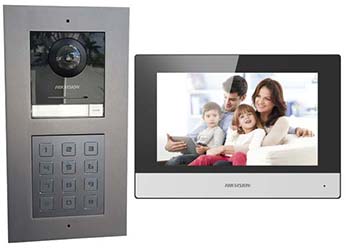
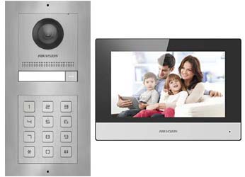
Hikvision IP Gate Intercom with Built in Digital Keypad and Monitor
2Mpx camera with fisheye lens, night vision flush or surface mounting anodised aluminium or stainless steel with built in keypad to open gate. Calls a monitor inside or Smartphone with an App. 12V or PoE. Can open a second gate from monitor or phone.
Data Sheet
Features
A modular system including HIK-KH6320-WTE1 Monitor, HIK-KD8003-IME1 camera module, HIK-KD-KP Digital Keypad and a choice of either HIK-KD-ACF2-P double gang flush mounting or HIK-KD-ACW2 double gang surface mounting housing for the Aluminium version, the stainless steel product codes are the same but with an "-S" at the end.
The outdoor station is fully weather proof (IP65)
The camera module is 2 Megapixel (1080P) HD Camera for sharp picture with a wide viewing Angle (180o), works in very Low Light and has built in Infrared LEDs for night time viewing.
Indoor Monitor is 7" Flat Colour Touch Screen with a resolution of 1024 x 600px
The camera module and monitor maybe connected with a Network cable or WiFi, if the camera module requires a WiFi connection an Outdoor WiFi Access Point must be added (not included).
Camera module and Monitor are Powered from 12VDC or Standard 48V PoE (Power over Ethernet)
The digital keypad is connected to the camera module with a small patch lead for data and power.
The digital keypad is connected to the camera module with a small patch lead for data and power.
Each Outdoor station can call up to 6 Monitors at once. Note: Need to have at least one indoor monitor.
If more than one Indoor Monitor is used selective calls can be made between monitors for room to room voice only communication.
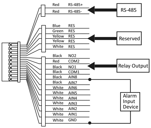
Monitor has 8 Alarm inputs that can be setup to send alerts to Smartphone App.
Can be used to call Smart Phones with and App anywhere in the world. App is free for Apple or Android Smartphones or Tablets and is linked to the monitor.
All calls are logged and snapshot taken when ever call button to a built in 128Mb of memory. This can be expanded if an SD card is fitted to the monitor maximum 32Gb.
Digital Keypad can operate one gate with one Access Code
Opens a gate either a pedestrian gate with electric lock or driveway gate operator. Note: if using PoE to power the outdoor station a separate power source is required for electric strike or magnetic lock.
Smartphone/tablet App or Indoor Monitor can indicate whether gate or door is open or closed. Note: requires an electrical connection to gate motor/lock that has monitoring facilities or installation of position sensor for this to work.
Has Tamper alarm in case someone tries to pry the outdoor station off the wall.
Monitor and Smart phone App can also connect to and view stand alone IP cameras or those on an IP video surveillance system for different viewing angles. It can also access video recorded on an NVR.
Camera module can be viewed anytime from Smartphone, Tablet, Indoor Monitor or IP video surveillance system.
Outdoor Station Specifications
Image Sensor: 2 Megapixel (1080p) CMOS
Angle of View: 180o wide x 96o high fish eye
Video Compression: the latest H.264
Night Vision: Works in very low light and has Infrared LEDs for night vision.
Material: Aluminium or Stainless Steel
Power: Requires 12VDC at the gate that can be taken from an automatic gate operator or power adaptor (not included) or Powered through an Ethernet Cable (PoE). - 120mA standby 830mA in use.
Flush box fits into a rectangular hole 237mm x 134mm x 56mm
Monitor Specifications
Dimensions: 200mm x 140.0mm x 15mm
7" colour TFT-LCD capacitive touch screen.
1024 x 600 pixel resolution
SD card maximum 32Gb, has 128Mb built in memory.
WiFi: 2.4Ghz
BUY NOW
Installation Instructions
Because the outdoor station is a modular system the camera module and digital keypad module are connected together with a small patch lead, with other wiring back to the router and to the gates connected to the camera module. If powering from 12VDC this is also connected to the camera module provided from a power adaptor or from a gate motor, the digital keypad module also needs setup on the module itself as well as from an App, more about this later.
Camera Module Includes:
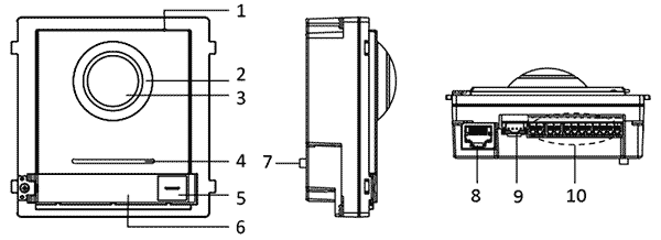
1) Microphone
2) IR Night Light
3) Camera
4) Loudspeaker
5) Call Button
6) Name Tag
7) Tamper Switch
8) RJ45 Network Socket
9) Output Socket for connection to Digital Keypad.
10) Input/Output Terminals.
Digital Keypad Module Includes:
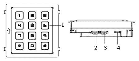
1) Keys Metal backlit.
2) Output Socket for connecting to an third module
3) Input Socket for connecting to Camera Module
4) Debug socket.
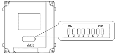
There is a small rubber plug in the back of the Digital Keypad that must be popped off revealing an 8-way DIP Switch. DIP 1 must be set ON and the rest OFF, this identifies the Digital Keypad as module one. The rubber bung must be put back in so the module is water proofed.
The are other modules that can be used include:
1) 5 button call module with name tags so the intercom can be used to call up to 6 different residences sharing the same gate (including the call button on the camera module). More than one module maybe added to call an additional 5 residences. If there are a lot of residences a scroll module and the digital keypad can be used.
2) Scroll Module has a small display showing how to enter a code to open the gate, how to call more than one residence with the digital keypad and has a list that can be scrolled of the different residences to call.
3) RFID Module can open a gate with an RFID card or tag rather than a digital keypad, is more secure when there are a lot of residences because they can't just tell all their friends what the code is.
4) Indicator Module has graphics that light up when a call is being made, a call is established and gate is being unlocked, which makes the Intercom more user friendly.
If a 2nd module is used it must have DIP 2 ON and the rest OFF, a 3rd module 1 and 2 ON and the rest OFF, a 4th module 3 ON and the rest OFF, 5th module 1 and 3 ON the rest OFF, 6th 2 and 3 ON the rest OFF, 7th module 1,2 and 3 ON the rest OFF and 8th module, 4 ON and the rest OFF.
Modules may be fitted into either a 1, 2 or 3 gang mount either surface or flush mounting.
Camera Module Wiring Diagram to Nice or King Gate Motors
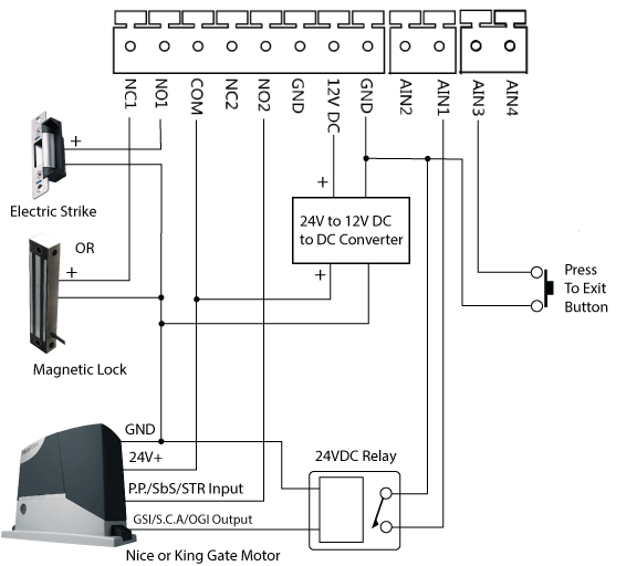
Nice and King gate motors, in fact all Italian Gates Motors are 24V and have only a 24V Output for accessories such as an intercom, which requires 12VDC so a 24V to 12V DC to DC converter is needed to power the intercom from the gate motor, although electric strikes and magnetic locks for pedestrian gates generally have the option of 12VDC or 24VDC so can be powered directly from the 24VDC. If powering the Intercom with PoE then the 12VDC power input isn't required, although separate power for an electric strike or magnetic lock is still needed from another source such as that from the gate motor. Because the Intercoms gate outputs share a common terminal and the Nice and King motors input for controlling the gate have a common 24V+ the electric strike and magnetic lock must have 24V+ switched to power them up.
The Press to Exit input actives gate output 1 only (NO1/NC1) and so does the digital keypad. Gate output 2 can be activated from the Monitor or Smartphone App.
Nice and King gate motors have a gate open light output so if the open status of the gate is needed this can be used to activate a 24VDC relay that's output is connected to AN1 input of the camera module, relays must be purchased separately.
Another way to know from a Monitor or Smartphone if the gate is open or not is to add an IP Camera outside that can see the gate, see IP Cameras for more detail on this
Camera Module Wiring Diagram to Dace or Centys Gate Motors
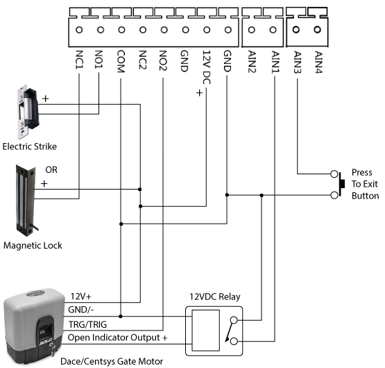
Dace and Centsys gate motors have a 12VDC output for accessories so can power an IP Intercom directly. This same 12V can be used to power an electric strike or magnetic lock too used for a pedestrian gate. They also have a gate open indicator or status output that can indicate to the intercom if the gate is open or not. Because Dace and Centsys motors input to control the gate has a common ground (GND) and the gate outputs of the intercom share a common, then the electric strike or magnetic lock must be switched to ground to power them up.
Outdoor Station Installation
The surface mounting version has a surface mounting box that screws to the wall on the surface with the cabling coming in from the wall. The modules then fit into the box with a patch cable run between the digital keypad module and camera module and all other wiring run to the camera module. The RJ45 network socket must have a Cat 5 or Cat 6 cable, with a suitable RJ45 plug fitted to it that runs to the home router or WiFi Access point that connects to the home router. The camera module maybe powered for a network cable using a standard PoE Switch or power adaptor then the 12VDC connection shown in the wiring diagram wouldn't be necessary although if it is to activate an electric lock for a pedestrian gate a power source is still required for the lock as this cannot be powered from PoE. A cover plate then fits around the modules holing them in place.
The flush mounting option requires a hole to be cut into the wall 237mm x 134mm x 56mm and a flush box fitted into the hole, the modules then fit into the flush box and a front plate is fitted to hold the modules in place.
Monitor Includes:
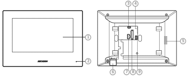
1) Screen
2) Microphone
3) Debugging Socket
4) RJ45 Network Socket
5) Loudspeaker
6) SD Card Slot
7) Input/Output Terminal for plugin flying leads
8) Reserved
9) Power Terminal for plugin flying leads, where 12VDC is connected 2-core coloured black and red.
Monitor Wiring Diagram
Activating the Monitor
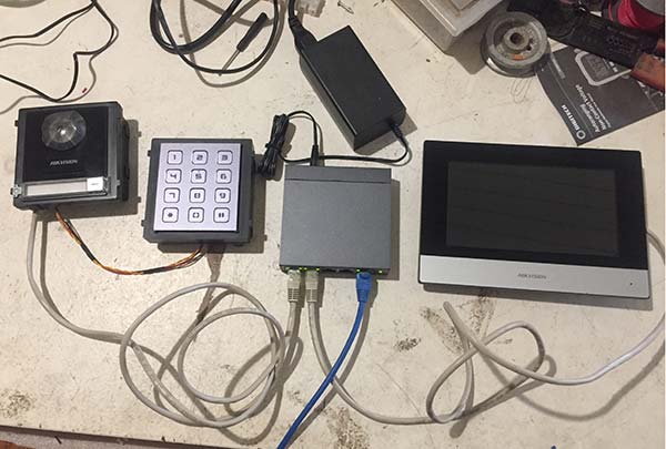
Its best to connect everything together on a work bench or the kitchen table before the final installation as it is easier to get everything working this way. Both the camera unit and monitor must be connected to the same home router that will be used in the final installation using network cables even if a WiFi connection is required for the final installation. All devices must also be powered that can be done by connecting them to a 12V Power adaptor using there 12V Power Inputs (see wiring diagrams above) or using a standard 48V PoE Switch they can be powered through the network cable as in the picture below.
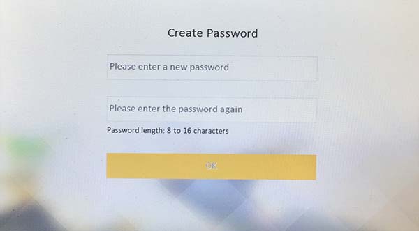
Setup begins with the monitor, when powered for the first time or after a factory reset the monitor must be activated, which is done by entering a password.
Setting the Monitors IP Address
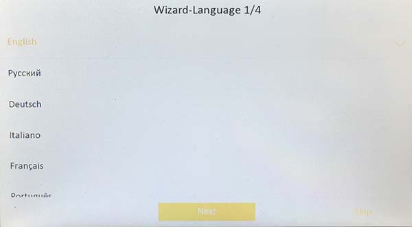
Once activated the setup Wizard is entered where stage 1 is selecting the language.
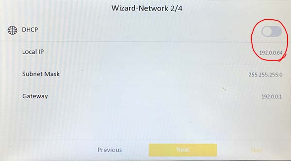
Then for stage 2 tap the DHCP slider and the Local IP address will be updated so it is compatible with the network the intercom is on. If it is already compatible there will be no change to the Local IP. If you are curious as to what an IP Address is see Setting Up IP Intercoms for a comprehensive explanation.
Activate Camera Module from Monitor
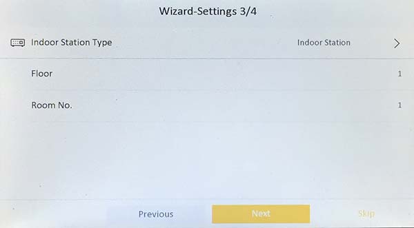
Stage 3 is for assigning a monitor to a specific room (residence) or floor if its in an apartment building, it is only necessary to change this if the Outdoor station is calling more than one residence otherwise just leave it at as it is.
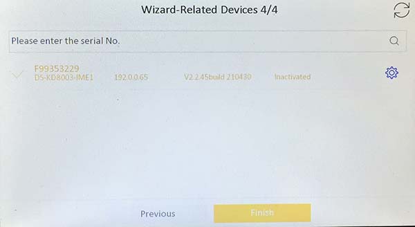
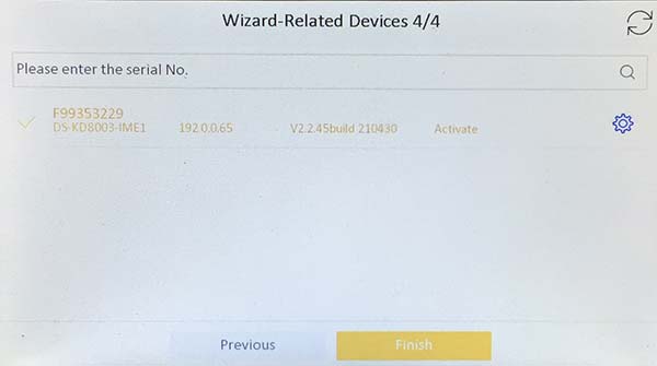
Stage 4 is activating Camera Modules, we have only 1 which should appear as below if it is on the same network even if its IP Address isn't compatible with the network. Tap the blue settings button to the right of the listing that will ask to activate or not, tap ok and the camera unit will be activated with the same password as the Monitor.
Setting Cameras IP Address from Monitor
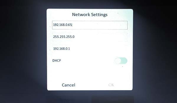
Tap the blue setting button again and this time it will bring up Network Settings popup, once again tap DHCP slider then ok. The IP Address should change, if not either it is already compatible with the network already or its a bit slow updating, tapping the blue setting button again should display any change in the IP Address.
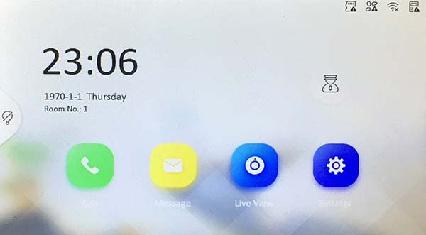
Another confusing thing is when the Camera Module is activated it shows it as "Activate" instead of "Active", its means Active, probably just a typo in the software. If you now tap "Finish" you will have the basics of the Intercom working and will be returned to the home screen.
Testing its working
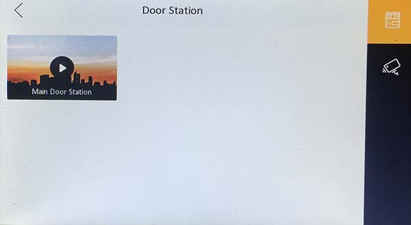
From the home screen if you tap "Live View" button ...
... a screen will open with a selection of door stations to view, if setup was successful then an icon will appear for our single outdoor station and if tapped ...
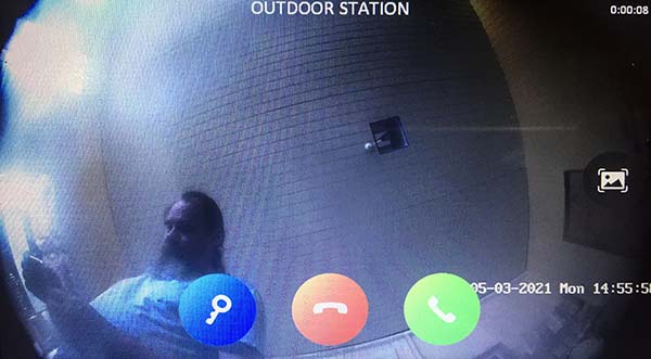
Making a Call
The camera on the outdoor station can be viewed. In this case the camera sees the workshop roof and the author of these instructions taking the photo below from the monitor, a Hikvision selfie so to speak. The blue button will unlock/operate a gate and green button establish an audio link so a conversation can be had with who ever is seen in the camera.
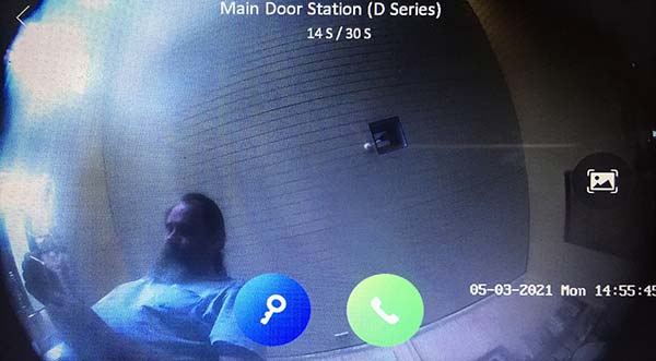
To further test the intercom is working the call button can be pressed to call the monitor that brings up a similar screen with the same buttons and one additional button, the green button answers the call and a red button that ends the call.
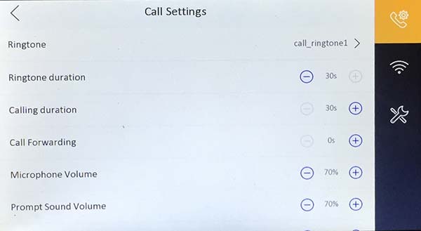
Change Call Settings
From the Home screen tap settings button to enter the settings screen, here you can change the ring tone, duration, volume etc...
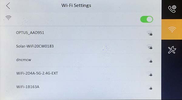
Setup WiFi
From the Settings Screen the WiFi can also be set by tapping the WiFi Button, tapping the enable WiFi slider at the top left and any WiFi routers with in range will appear, tap your router and enter your password and connect like you would do with your Smartphone and its done.
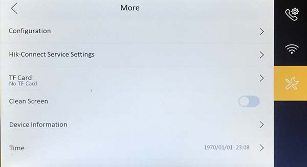
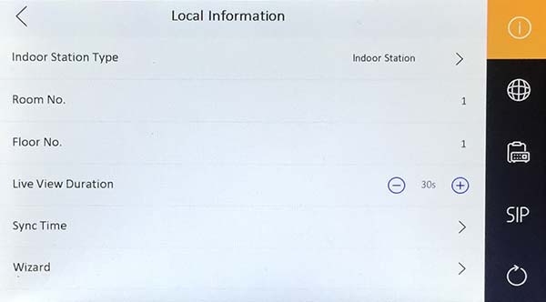
Setting the Date, Time and other settings
From the Settings Screen tap the More button where the date and time can be set, swipe screen up to see more settings.
Adding more than One Monitor
If adding additional monitors they must be activated and IP Address set as with the first monitor then from the setting screen if the monitor is a 2nd or 3rd e for the same residence then tap configuration and enter the password that was used to activate the monitor and the configuration screen is entered, here tap Indoor Station type and select extension.
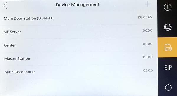
Adding a Second Door Station
A 2nd outdoor station can be activated and IP Address set the same as the first Outdoor Station was and then from the configuration screen (see adding more than one monitor) tap the Device Management Button to enter the Device Management Screen, where the IP Address of a 2nd Outdoor Station needs to be added so the monitor knows there is more than one.
Calling a Smartphone
Hikvision have an App call Hik-Connect that can be installed on a iPhone or Android Smartphone and be linked to the Monitor so when a call is made from the outdoor station it not only goes to the Monitor but also to the Smartphone too. See Installing Hik-Connect for details on how to do this and how to connect it to the monitor.
Adding Codes to the Digital Keypad.
This cannot be done from the monitor unfortunately, it can however be done from Hikvisions iVMS-4200 App for Windows or Mac computers that can be downloaded for free from the Hikvisions website. Running iVMS-4200 for the fist time you will need to register an account for security reasons and when opened for the first time you are presented with the following screen:
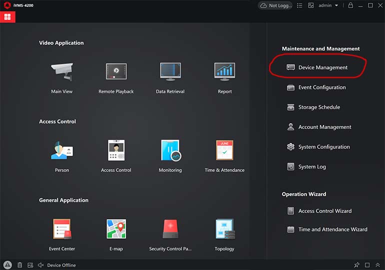
Click on Device Management then in the Device Management screen click Online.
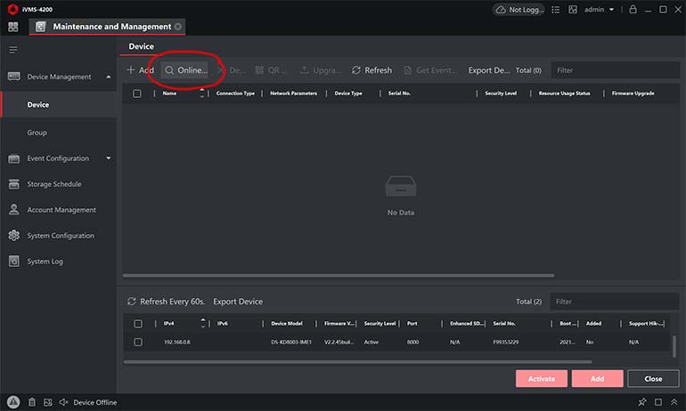
This will find what ever outdoor stations are on the network even if their IP Address aren't compatible with the router, each outdoor station is listed at the bottom, in this case we have only one. This App may also be used to activate the camera module and change the IP Address to something compatible with the network if needed, rather than doing this from the monitor, other wise if it was already done on the monitor then the IP Address should already be compatible and security level active.
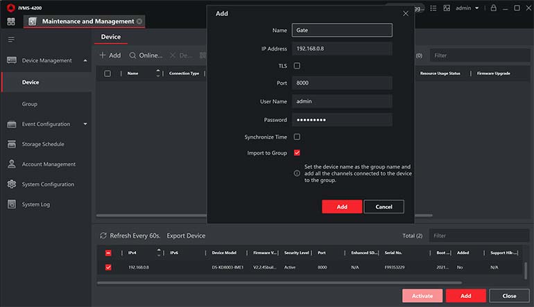
To be able to setup more than possible from the monitor select the outdoor station in the list at the bottom and the Add button will become active, click this and an add popup appears, give the camera unit a name enter the password that was given to the monitor when first activated as this would have been passed onto the camera module too if it was activated from the monitor, if activated from this App then enter whatever password was used.
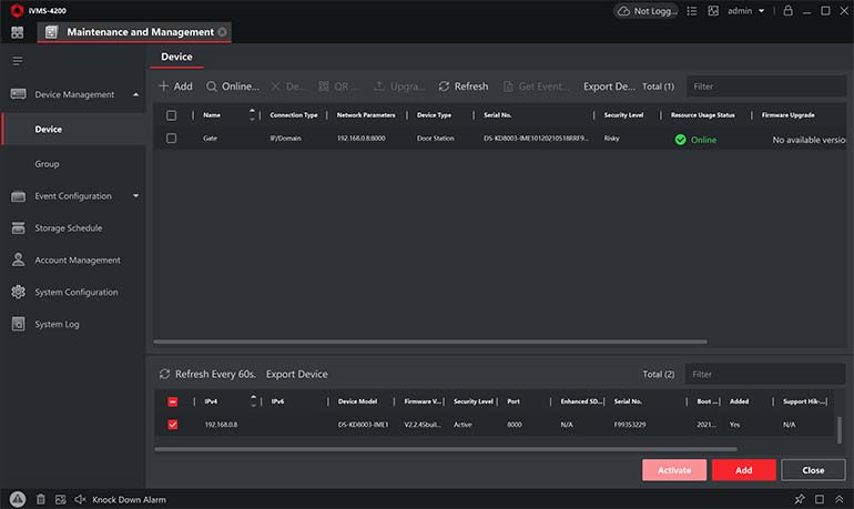
The camera module should appear in the device list and ne online (in green).
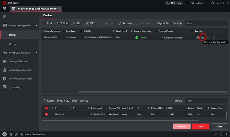
If it does appear online then to the right click the edit button and check the password is correct. If online click the remote configuration button (circled in red) ...
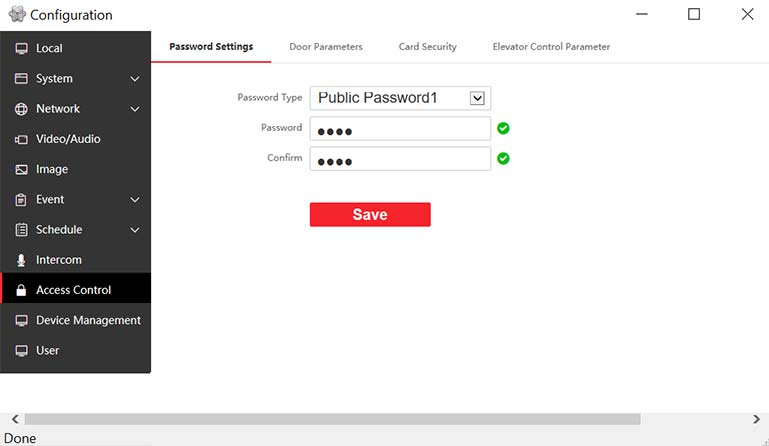
... and you will get access to the Outdoor Stations Camera Modules menu, which is on the device itself, you cannot get access to this camera module with a Browser like you can with other IP Devices. On the Camera Modules menu click Access Control and enter a numerical code into the Password and Confirm fields and save. Now on the keypad if you enter "#"numerical code"#" the gate will open, well a message will say so because you won't have an actual gate connected at this point.
Other aspects of the camera module can be set from this menu, click on the various menu options to find what can be adjusted. If you want to connect the Outdoor station to the router with WiFi then a separate Outdoor WiFi Access Point is required, which can be found at WiFi Access Point that includes links to instructions on how to set this up, which can be done at the same time as the other devices on a work bench or kitchen table.