
How to Install a Sliding Gate Motor (operator)
If you wish to find a suitable motor for your sliding gate see Motors for Sliding Gates
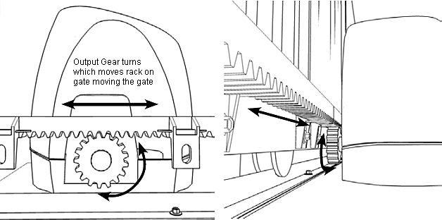
How Sliding Gate Motors work
The motor has an output gear that connects to rack on the gate, as the output gear turns the gate moves.
Preparing the Gate
The gate must open and close freely without binding anywhere along the way. Posts for sliding gates should be steel or seasoned hardwood that won't warp as this may cause the gate to miss the keeper over time and not work properly. If the gate has a guide post there must be at least 60mm (2 3/8") clearance for the rack, which is fitted to the back of the bottom rail of the gate. The motor needs a suitable concrete pad to be installed on that is level.
... READ MORE about installing pads for motors
Installing Cabling
If the motor is to be powered by 240V mains you will need an electrician to take care of this. The motor can be hardwired where the power cable is feed through the pad the motor is fitted to or a Power Point can be fitted next to the motor. If using Low voltage or solar power a low voltage cable can be feed through the motor pad and to a transformer or solar panel
... READ MORE on Power options for automatic gates.
Choosing the correct motor
There is no such thing as one motor for all gates, different motors are suitable for different applications.
... READ MORE about choosing the correct sliding gate motor.
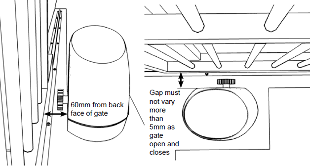
Positioning The Sliding Gate Motor
Place the motor on its pad about 60mm (2 3/8") from the back face of the gate.
Place a length of rack on the output gear of the motor against the back face of the gate to check that it lines up with the output gear correctly. Open and close the gate to see that this is consistent for the whole length of the gate. The bottom rail must be straight otherwise the spacing between it and the motor may very too much and the rack not contact the output gear in places, which could stop the gate working.
The rack must fit on the bottom rail of the gate for the entire open and close movement. If it comes off the bottom then the motor will need to be packed up, if it comes off the top then the gate wheels may need to be packed to lift the gate higher or other means for fitting the rack may need to be implemented. The motor pad may also be lowered if necessary.
Fixing the motor to the Pad
Most sliding gate motors have a base plate that either bolts to the pad and then the motor bolts to the base plate, although some motors bolt directly to the pad. Some Italian motors have bolt pins that are too be concreted into the pad, which isn't all that practical although these can be replaced with normal bolts.
Packing the Motor up if needed
A couple of lengths of suitably sized box section aluminium or galvanised steel can be used to pack the motor up. These would ideally have holes drilled into them so they can be dyna bolted to the concrete pad or metal screwed to a metal pad then the motor screwed to the box sections where ever it can be.
It's important the the motor is fixed near the edges so it is firm and doesn't move at all when the gate is moving.
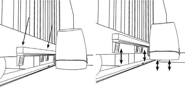
Fitting Rack for a Sliding Gate Motor 1
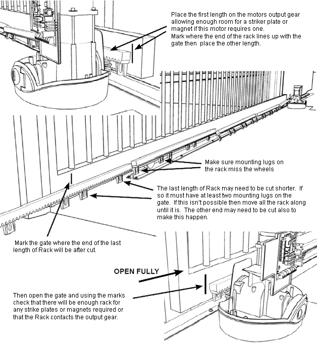
Before fitting the rack lay it out behind the closed gate to see how it will line up.
Fitting Rack to the Sliding Gate Motor 2
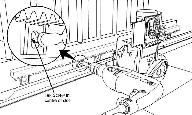
To fit the rack start with the gate nearly closed and place the first length of rack on the motors output gear aligned with the mark made previously on the gate. Using an electric drill attach the rack using tek screws in the centre of the slots in the mounting lugs.
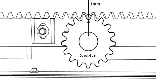
Adjust the height of the rack above the output gear so there is a gap of about 1mm (1/25").
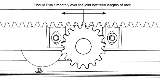
Fitting Rack for a Sliding Gate Motor 3
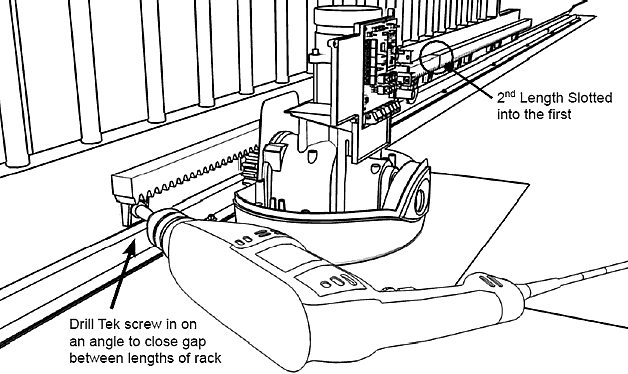
When fitting the second length of rack make sure the that it is firmly clipped together so the tooth spacing is consistent at the join, other wise the gate may jump when the joint goes over the output gear.
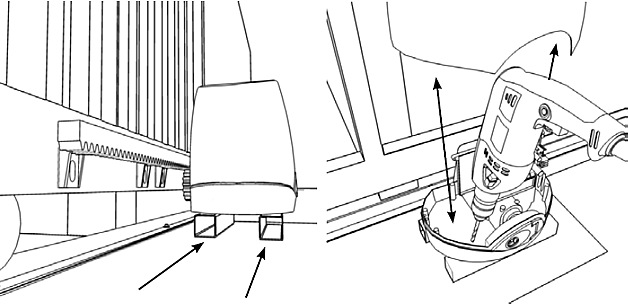
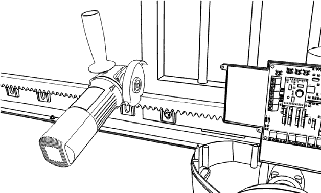
Fitting Rack for a Sliding Gate Motor 4
Once all the lengths of rack are fitted cut the last one to length if necessary using an angle grinder with a steel cutting blade because the rack has a steel rod in the middle.
How to get it all Working
Do not connect any photocells, digital keypads, intercoms etc... yet, get the gate working without these first to reduce confusion if something's not working correctly. Power up the motor then set the remote controls.
... READ MORE about how to set remote controls to work on your motor
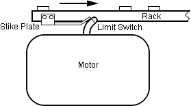
Then set the open and close limits for the gate. There are different methods for determining where the fully open or closed position of a sliding gate is. The most common using strike plates fitted to each end of the rack that contacts a spring loaded wand sticking out of the motor that activates limit switches inside the motor.
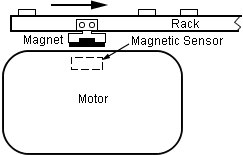
Other motors use magnets instead of striker plates with a magnetic sensor in the motor. There are also motors that use one only magnet placed near the closing end as a reference only not a limit. These also have an 'encoder' that is a rotation counter of the motor used to determine how far the gate moves between the fully open and close positions with the reference marker making sure it stays on track.
Once the strike plates or magnets are fitted all motors need to run through a learning process that powers the motor open and closed to learn where the limits are. You will need to refer to the installation manual on how to do this as it is different with each motor.
Now connect accessories one at a time and test their operation such as Photocells, In Ground Vehicle Detector, Digital Keypad, Intercom etc...