
Installing Worm Drive Swing Gate Motors
How They work
Worm Drive Gate Motors or Linear Swing Gate Motors as they are also known come in two varieties, the piston worm drive that has an inner tube that slides in and out called the translating tube that connects to the gate and the open worm worm drive, which connects to the gate from underneath the motor.
READ MORE about the different types of swing gate motor
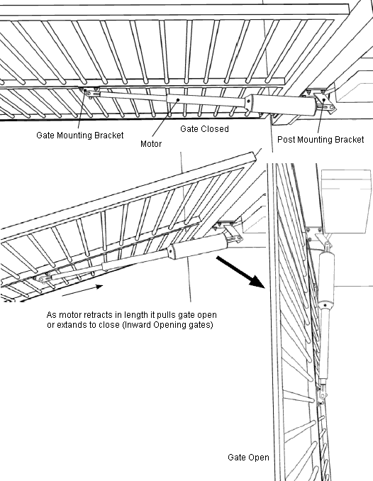
Both varieties have a geared electric motor that turns a 'worm' or 'acme screw' as the engineers like to call it that drives a nut in a straight line or 'linear' direction. This nut then connects to the gate mounting bracket (GMB) to either pull the gate open as it retracts or push it closed as it extends (vise versa for outward opening gates). The amount the nut can travel is called the 'stroke', which can vary from 320mm (13") to 500mm (20").
Worm drive motors relay on hard stops to set the open and close limits of the gate and use either running time or distance travelled to determine when to start slowing down for a soft stop or reverse if the gate is obstructed. To get the distance travelled a motor will have an encoder built in, which is basically a rotation sensor that feeds back to the controlling electronics one or more impulses for each rotation of the motor, these are counted by the controller to read the distance travelled.
To Keep Things Simple
The most difficult part of installing a worm drive swing gate motor is the making up of the mounting brackets. Because swing gates vary quite a bit there is no "one bracket that fits all" for installing the motor, even the so called 'adjustable' brackets that are available with some motors that 'require no welding' don't fit the gate all that well most of the time and don't look too good either.
Most motors from the factory come with the tongue part that the motor fits to only with the intention that the installer design and make the mounting brackets themselves to suit a particular gate. We at Grant's Automation understand that this is a little too much to ask the average installer as the setup of the mounting brackets isn't all that straight forward, let alone having to weld them together, so we have come up with some standard designs that will work with the most common gate layouts found in Australia and New Zealand. These designs can be found in the listings of parts that come with each worm drive swing gate motor kit. You can either choose one of these bracket options with the motor order and it will be welded up for you, zinc plated and be included with the motor ready to bolt or screw on and will just work, although this may add a week or so to the delivery time OR you can not include these brackets in the order and you will get the tongues only so you can make your own brackets straight away and the way you want.
Grant's Automation's Mounting bracket designs are copyrighted so you cannot make these without written permission from Grant's Automation. If you can't find a set of brackets that suits your gate then feel free to send us an enquiry as we can quote for the custom design and manufacture of mounting brackets specifically for your gate with details supplied by you. All brackets are welded, dressed and zinc plated so they won't rust and will look nice. With 30 years experience installing gate motors and using the latest 3D computer design tools, the brackets we design are tested with a virtual simulation of a gate in a computer before anything is made, so the installer can be rest assured that the brackets will get the best performance out of the motor and make it last as long as possible. We know more about fitting gate motors than the manufacturers because we've installed gazillions of them over the years and are fussy about they way they work.
Double Swing Gates
Require two motors, one for each side of the gate, but only one control box, which controls both motors to keep them synchronised so requires a cable across the driveway. Normally only a two core cable is required if the motor relies on running time but if it uses an encoder it needs a 6 core cable with two of these heavy duty for the motor and the others lighter duty.
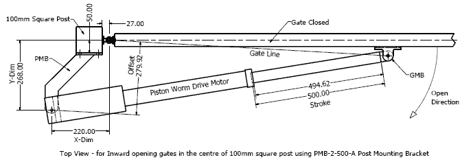
Positioning of the Post Mounting Bracket (PMB) is Critical
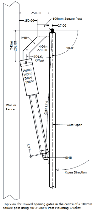
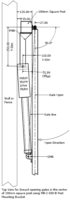
The point where the motor mounts onto the Post Mounting Bracket (PMB) is critical to the way the motor works, it must be offset from a line between the hinge and the point where the motor fits onto the gate (the Gate Line) before the gate will move. The larger the offset the better the motor will hold the gate and the more force it can apply. The offset must be maintained throughout the whole opening cycle so the point where the motor fits onto the PMB must be set back on a diagonal from the hinge defined by X and Y dimensions. The value of these dimensions is determined by a number of factors including: the stroke length of the motor, opening angle of the gate, length of the GMB, positioning of the gate relative to the hinge etc...
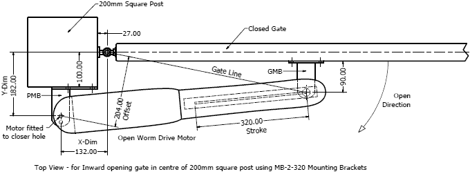
Clearance Behind the Open Gate
An automatic gate cannot open hard up against a wall or fence, there needs to be some clearance. The amount of clearance depends on the size of the gate and the motor, although the PMB can be made up to fit into a small amount of space, which also has the effect of the motor holding the gate better in the close position but not so good in the open position. This also effects the speed of the motor that will run slower with more force from the close position and faster with less force as it approaches the open position. The piston worm drives fit into a much smaller space then the open worm drives.
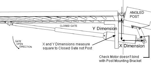
If the Post is on an Angle
The X and Y dimensions should be measured square to the closed gate not the post, which is a common mistake made causing the dimensions to be off and gate not work properly.
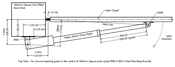
The Distance the Gate is from the Back of the Post
If the gate is set in the middle of a wide post then a longer stroke piston worm drive will be needed otherwise the gate will need to be near the back of the post.
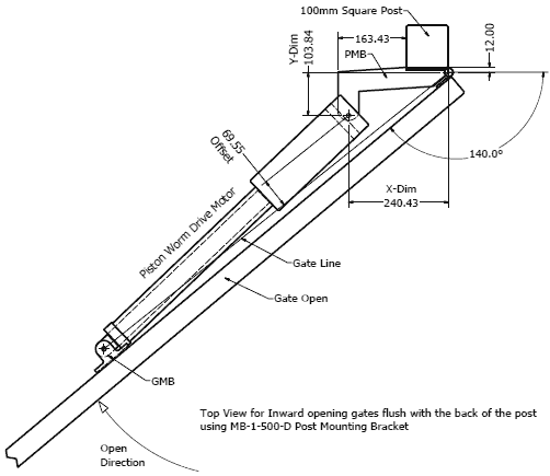
Wider Opening Angle
Open worm drives can only open a gate to 115o because the body of the motor extends past the GMB as it opens and can clash with the gate limiting the opening angle.
Piston worm drives don't have this limitation so can open a gate to 140o although a longer stroke is necessary because the ability of the motor to apply force to the gate is reduced the wider the opening angle is and a longer stroke compensates for this.
Outward Opening Gates
Gates can be made to open outwards with the motor inside the property, although the setup of the motor is a little different to inward opening gates. The motor must extend to open and retract to close, which is the opposite way around to inward opening gates.
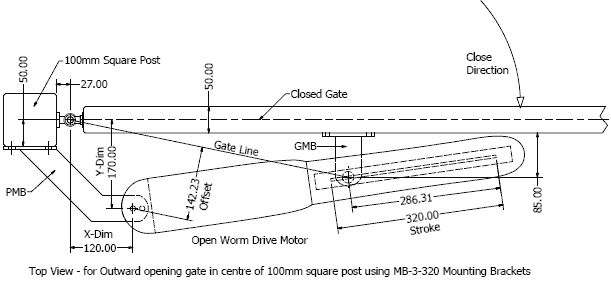
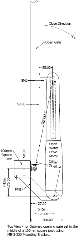
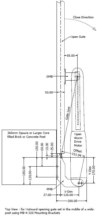
For outward opening gates the motor must extend to open and retract to close, which is the opposite way around to inward opening gates. Outward opening gates require larger Post Mounting Brackets because they must extend into the gate opening, although can fit on very wide posts with the gate set in the centre.
Increasing the Speed of the Motor
If the X and Y dimensions are made smaller the speed of the motor is increase although this also sacrifices the amount of force the motor can apply to the gate so is only recommended for lighter weight gates well under the maximum limit for the motor.
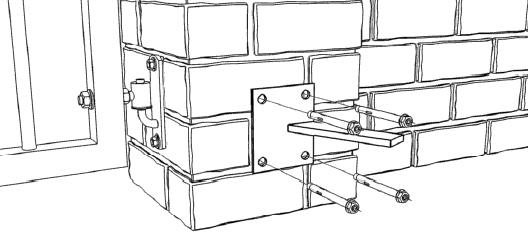
Fitting the Post Mounting Bracket
If the post is steel or timber you should bolt the bracket through the post with M8 cup head bolts so it doesn't pull off although with steel posts you could drill and tap 12mm (1/2") bolts or with hardwood use batten screws.
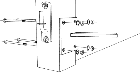
If the Post is Brick or Concrete Block it must be core filled with concrete and you must use dyna bolts that are large enough to reach the concrete core filling otherwise they may pull out. Normally M16 x 140mm is required for brick.
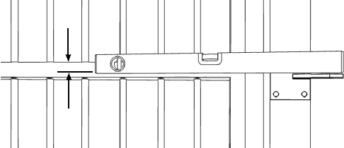
Height of the Post Mounting Bracket
The Post Mounting Bracket must line up with the bottom or middle rail of the gate depending on how the Gate Mounting Bracket fits. In some cases the top rail can be used too. Use a spirit level to align the Post Mounting Bracket with the rail.
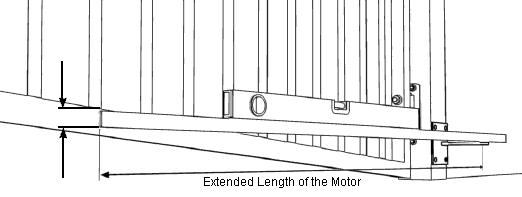
If fitting to the bottom rail and it is raked you will need to mark the rail where the Gate Mounting Bracket will go by taking the full extended length of the motor from where the pivot point of the motor will be on the Post Mounting Bracket then use a spirit level and straight edge to align the Post Mounting Bracket. The motor should be level.
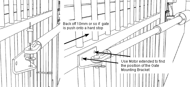
Fitting the Gate Mounting Bracket
Before fitting the Gate Mounting Bracket you must firstly fit the Post Mounting Bracket and fit the motor to Post Mounting Bracket then you need to extended the motor out fully to find the position of the Gate Mounting Bracket, although if the gate is closing against a hard stop back it off a little t allow the motor to apply some pressure on the hard stop. Piston drive motors can mount as close as 32mm (1 1/4") from the inside of the gate rail whereas open worm drives need at least 90mm (3 5/8") so the body of the motor doesn't strike the gate at any point in the open cycle.
Normally you need to install the control box before you can extend the motor out although some motors you can do this by hand simply manually releasing the motor then fit the bracket to the motor so you can pull it out to maximum extension.
Open worm drives can normally be driven to the end of the motor, which is a hard stop or they have adjustable stops built in.
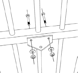
If the gate is made from aluminium Bolt the Gate Mounting Bracket through the gate with Cup Head Bolts because they look nicer from the front and will hold a lot better than Tek screws. Tek screws will hold onto a steel frame well enough in most cases.
If you prefer not to see anything from the front you can use Nutserts that work a bit like a rivet but have a threaded hold in the middle so you can screw a bolt in that. These work well but you do need a special crimping tool to use them, which is expensive so unless you're doing this all the time its more economic to bolt through with cup head bolts.
How to Get it all Working
If the motor has a separate control box and you haven't installed this already then do so. Do not connect any photocells, digital keypads, intercoms etc... yet, get the gate working without these first to reduce confusion if something's not working correctly.
READ MORE about how to install a control box
Power up the motor then set the remote controls.
READ MORE about setting remote controls to work on your motor
Then set the open and close limits for the gate.
READ MORE about setting Open and Close Limits
Now connect accessories one at a time and test their operation such as Photocells, In Ground Vehicle Detector, Digital Keypad, Intercom etc...