
Cutting and Drilling No-weld Aluminium Extrusions and Related Materials
Like all systems similar to No-weld there are always technicalities of how to cut and drill materials to be assembled accurately and cleanly. Because No-weld requires no welding the mitred corners of the frame need to be cut cleanly and accurately with no burrs or gaps. This page covers how to do this and other technicalities for anyone interested in making gates or fencing kits up themselves including:
What saw and stand to use and how to set it up for accurate cuts - making accurate mitred cuts - drilling holes for the corner brackets - making your own corner brackets - cutting slats, battens or vertical tubing - drilling holes into No-weld framing for slats, battens or vertical tubing - cutting channels and angles for fitting sheeting - cutting spacers.
The Saw
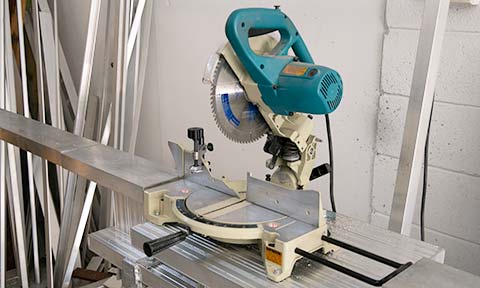
To cut aluminium extrusions cleanly and accurately with very little burring you need a good quality mitre saw of a good brand with a good blade. A 'non sliding' mitre saw will do for cutting No-weld framing, slats and battens. If you want to make your own corner brackets or cut larger material you will need a 'sliding' mitre saw.
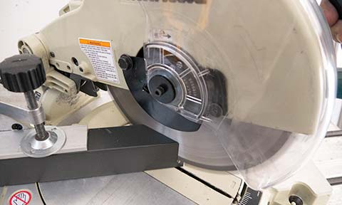
The Saw Blade
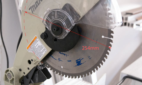
The blade will need to be at least 254mm (10") for most cutting or 305mm (12") to cut larger material with a non sliding saw. A sliding saw can be as small as 209mm (8 1/4"). For a nice clean cut in aluminium we've found the Irwin brand of blades work really well. Also wax on blades helps get a burr less cut and extends the life of the blade.
The Saw Stand.
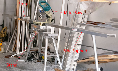
If you're planning on making No-weld gates on a regular basis a good stand for the mitre saw is a must. One with side mounts for holding the material in place is best that also has a stop for cutting many lengths of slats or tubing the same length, rather than having to measure each length one at a time.
Checking the Accuracy of the Saw
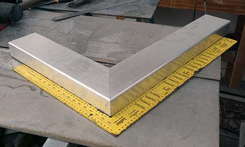
We have tried many ways to check if a saw is cutting angles accurately or not and have found the best way to do this is to simply cut the ends of two lengths of 100mm x 50mm aluminium box section or similar at 45o, then check if they make a 90o angle when fitted together using a builders square.
Getting the Saw Accurate
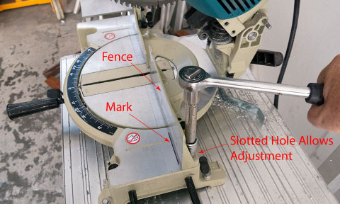
If a saw is not cutting accurately the fence can be adjusted by first marking where it currently is, loosen the fence screws (which have slotted holes) then adjust the angle in the direction that will get the angle closer to being correct, tighten the screws back up then recheck by mitre cutting material as mention before.
Waxing the Saw Blade
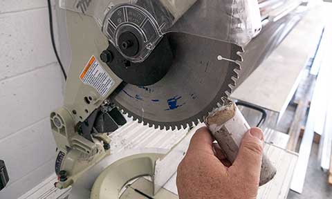
Wax on the blade lubricates it reducing localised heat so the blade cuts cleaner with less burrs and lasts longer. To put the wax on the blade it normally comes in stick form so just rub it on the teeth of the blade making sure you don't end up with larger blobs as they will just fly off and make a mess.
Making Accurate Mitred Cuts - First Cut
Never assume the end of a length of extrusion has been cut accurately, unless you have just made the cut so know for sure that it is correct. Always set the outer face of the extrusion towards you and clamp firmly the part of extrusion that will be used because if the material moves at all when cutting the cut won't be accurate.
Making Accurate Mitred Cuts - Measuring
If measuring mitred corners the outer face of the extrusion must face up then measure from the end that was just cut to the position of the second cut, mark it so the edge of the mark is the edge of the measurement so it doesn't matter how wide the mark is as it is the edge you're going by.
Making Accurate Mitred Cuts - Marking
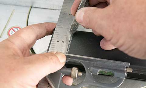
Mitred cuts are more difficult to get accurate than right angled cuts, the secret to getting them accurate particularly if the extrusion has rounded edges is to mark the outer face all the way across with a combination square. This gives a clear accurate mark to line the edge of the saw blade up with.
Making Accurate Mitred Cuts - Second Cut
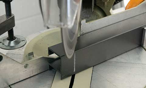
Place the length on the saw with the outer edge towards you, line the mark up with the saw blade so the edge of the blade is on the correct side of the mark and clamp the material firmly in place on the part that will be used. Clamping is necessary because if the material moves at all when cutting the cut won't be accurate.
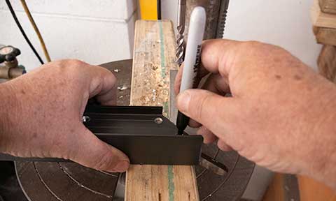
Drilling Holes for No-weld Corners
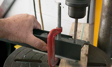
7.5mm diameter holes need to be drilled into the ends of each length of No-weld framing for the corner brackets. This is done by fitting a jig into the open back of the extrusion and clamping it in place with a small clamp. A small piece of aluminium flat bar is necessary for the front face of the frame so the clamp doesn't scratch it.
Making your Own Corner Brackets
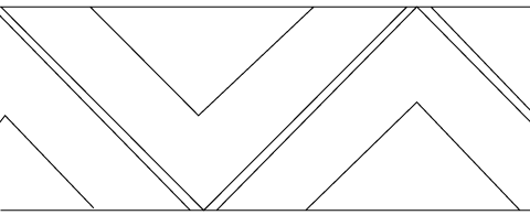
Corner Brackets can be cut from a length of 100mm x 10mm aluminium flat bar using a drop and slide mitre saw. If they are cut at 45o you can get more from one length. The main cut is done on the mitre saw then the small piece removed and inside corner cleaned up with a thin blade on an angle grinder.
Drilling Holes in the Corner Brackets
If the corner brackets don't have holes in them already you can use a length of pre-drilled piece of No-weld framing as a template for marking the corner bracket holes. Simply slide the pre-cut corner bracket into the end of the extrusion, align it up with the corner, mark the middle of each hole and drill 6mm diameter holes.
How the Tek Screws hold the Corner Bracket
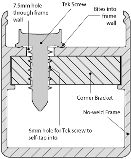
The holes through the frame wall for the tek screws are 7.5mm diameter, which are large enough to allow 14g tek screws to pass through with enough clearance around them so the squareness of the corner can be adjusted.
The 14g tek screws self-tap into 6mm diameter holes in the corner bracket and have ridges around the bottom edge of their heads that bite into the surface of the frame when tightened, pulling everything up very firmly and holding the position of the tek screws that was set when squaring the gate up.
Cutting slats, battens or vertical tubing - Number of
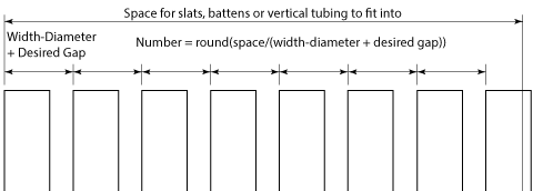
Before you start cutting you need to know how many slats, battens or vertical tubes to cut as follows:
Number = round(space / (slat or batten width or tube diameter + desired gap)).
Space for gates with horizontal slats is the height less width of any top or bottom rails; for gates with vertical slats or tubes set into the frame space is width of the gate less the width of the stiles. Gates with slats or battens fitted to the front of the frame space is just the height or width of the gate.
This is then rounded down to find how many will fit in the space with the desired gap.
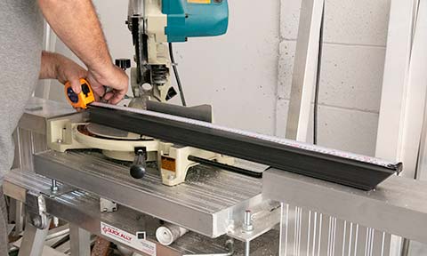
Cutting Slats, Battens or Vertical Tubing - Using a Stop
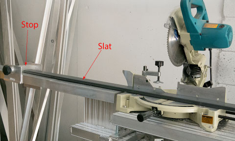
If a gate frame is square then all slats, battens or vertical tubing that goes on the gate are cut to the same length so rather than measuring each one individually a mitre saw stand with a stop can be used where the first length is measured and saw set up to cut but a stop is moved to the end so the next length is moved up against the stop to cut.
Drilling Holes for Face Mounted Slats or Battens - 1
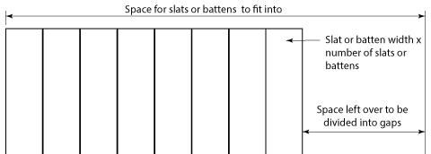
Before drilling holes for vertical tubing into No-weld framing the centres between tubes is required. We found the number of slats or battens using a desired gap but this generally needs to be a little more or less for the slats or battens to fit evenly on the gate.
exact gap = (space - width x number) / number -1.
Where 'space' is the height of the gate for horizontal slats or width of the gate for vertical slats or battens, the 'width' is the width of the slat or batten and 'number' is the number of slats or battens. The '-1' is because we need the number of gaps and with face mounted slats or battens there is one less gap than number of slats or battens.
Drilling Holes for Face Mounted Slats or Battens - 2
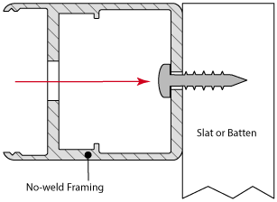
To fit slats or battens to the front of a No-weld frame, holes can be drilled through the back and front for screws that attach the slat or batten that remain hidden inside the frame.
To space these holes out correctly the leading edge of each slat or batten must first be marked. To do this use the methods above to find the number of slats-battens and exact gap between them.
To get the leading edges of each slat or batten use a calculator or spread sheet to make a list of how far each leading edge is from the edge of the gate. Each leading edge is the slat or batten width + exact gap added to the previous leading edge with at least 2 decimal places to minimise accumulative error.
We have made up an Excel spread sheet for making this list that you are free to download here: Face_Mount_Spacing.xls
Drilling Holes for Face Mounted Slats or Battens - 3
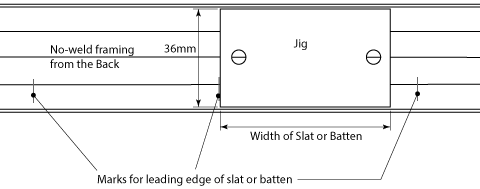
You now need to drill a hole near the edges of where each slat or batten will be. These are best marked using a template made from flat material with holes drilled where the screw holes are to go and lined up with the leading edge mark for each slat or batten. Pilot holes should be drilled first, which normally are the size of the holes for the screw threads to pass through for the front wall then the final holes drilled into the back wall large enough for the heads of the screws to pass through.
See Aluminium Slats on the front and Aluminium or Wood Batten Gates for more information on how these gates are assembled.
Drilling Holes for Vertical Tubing
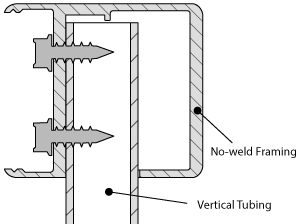
To fit vertical tubing into a No-weld frame, holes need to be drilled into the side wall(s) for the tubing to pass through that are then screwed to the frame from the open back so screws are hidden by the clip on cover.
To space these holes out correctly find the number of vertical tubes required using the method above then find the gap between verticals: gap =
(space - (diameter x number) / number + 1.
Where 'space' is the space between the inside of the stiles, 'diameter' is the diameter of the tubing, 'number' is the number of tubes and the '+1" is because there is one more gap than number of tubes.
To get the centre of each vertical tube use a calculator or spread sheet to make a list of how far each centre is from the edge of the gate. The first centre being: the frame width + gap + tube radius then each centre from here on will be added to the previous centre + tube diameter + gap with at least 2 decimal places to minimise accumulative error.
We have made up an Excel spread sheet for making this list that you are free to download here: Round_Vertical_Inset_Spacing.xls
Cutting Channels or Angles for Sheeting
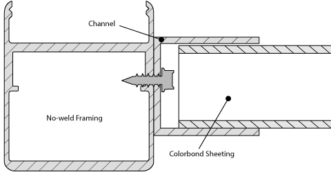
When fitting Colorbond or laser cut sheeting into a No-weld frame it is quicker and more accurate to fit a channel or angle to the side of No-weld Frame before it is cut so they can both be cut at the same time. To do this measure the approximate length of the frame member then mark and drill holes for screws or rivets used to attach the channel or angle to the frame starting 200mm from each end and then approximately 300mm apart in between. Channels can be tek screwed and angles riveted to the frame.
Cutting Slat Spacers Front View - 1
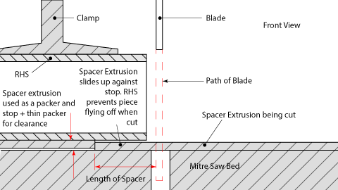
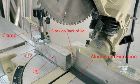
To cut slat spacers accurately from the a No-weld spacer extrusion a jig is needed on a mitre saw made from a piece of RHS aluminium clamped to a short length of the same spacer extrusion that is being cut, which is used as a packer and a stop to set the length. Another thin packer is also needed so the material to be cut can slide in easily.
Cutting Slat Spacers Top View - 2
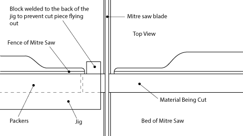
The RHS not only holds the packers in place it also prevents the cut piece from flying away, which is not only dangerous but the cut piece may never be seen again. The RHS needs to have a small block of aluminium welded to the back of it to fill in any gap in the fence of the mitre saw as the blade pushes cut pieces in this direction.
Cutting Slat Spacers - 3
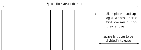
The method used above to find the exact gap between slats relies on all slats being exactly the same width, but when cutting spacers to go between slats this gap needs to be very accurate and slats vary in width by up to 0.4mm in the milling process and another 0.3mm can be added if powder coated. You may think this is only a small amount but if you add 0.7mm to 20 slats this could be a 14mm inaccuracy at the end.
To find the accurate length of the spacers you will need to lay all slats down on a flat scratch free surface hard up against each other and measure how much space they actually take up then what ever space is left will be divided as follows:
gap = space left / number of gaps.
The number of gaps for frame-less = number of slats - 1
The number of gaps for gates with slats set into the frame = number of slats + 1.
Cutting Slat Spacers - 4
To cut spacers accurately set the packer on the jig to the correct length using a steel ruler measuring from the packer to the edge of the tooth on the blade of the mitre saw. Once the cut is made leave the saw down with the trigger off and wait until the blade stops spinning before lifting it up, otherwise the piece could catch on the moving blade.
Cutting Slat Spacers - 5
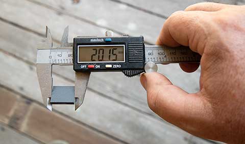
To get the length of the spacer accurate, once the first one is cut, measure it with a pair of calipers and if not correct adjust the packer a tiny amount in the correct direction then cut a second spacer and measure this. Repeat until it is exact. Ideally use scrap material for this.
Cutting Cylindrical Back Cover Spacers
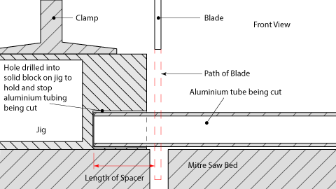
The back cover spacers are 10mm diameter aluminium tubing cut 12mm long and are used when fitting hardware to the back of a No-weld gate. See Guide to Fitting No-weld Hardware. The jig for cutting these has a hole drilled into a solid end of box section so a length of tubing can be inserted and stops it going anywhere when cut.