
Guides and Stops for Sliding Gates
Sliding Gates require a guide system to hold the gate up even when moving and stops so it doesn't come off the guide system and fall over.
If you want to buy Guides and Stops see Sliding Gate Hardware
The Keeper
There is a keeper or catcher bracket that a sliding gate closes into so is a guide for the gate and hard stop preventing the gate closing too far and holds the top of the gate firmly in place when it's closed.
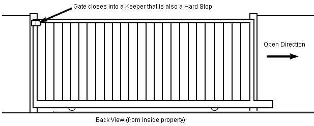
The keeper is flared to allow for a situation for when the wind or other force on the gate may cause it to be out of alignment and it guides it into place. Normally a sliding gate overlaps the receiving post by 50mm (2") or so and if fitted to a narrow metal or timber post the keeper must be towards the back of the post and have a suitable base plate for fixing.
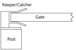
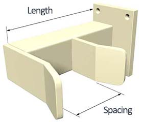
The length of the keeper and spacing between tines is set depending on how far the gate is to be from the back of the fence and the thickness of the gate.
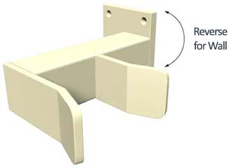
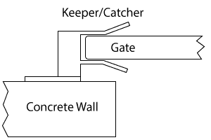
Keepers fitted to concrete or brick walls have can have their base plate reversed so they aren't too close to the edge of the wall because this could crack the corner of the wall when holes are drill for the fixings.
Guide Rollers
A sliding gate must also have a guide system to hold it up while it moves. The simplest way to do this is using a pair of rollers.
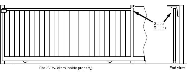
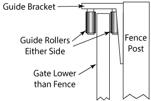
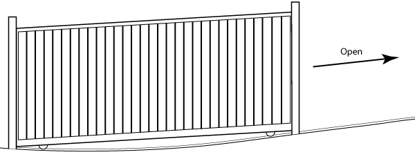
Guide rollers either side of the gate are suitable if a gate has cladding set in the middle of the frame or horizontal slats are used on the front of the frame and the gate is either on flat ground or both the top and bottom rails are raked on a driveway that slopes across. If there is a slight slope across the driveway and the top of the gate is to be level then longer rollers can be used. Normally the gate will be lower than the fence from open to close.
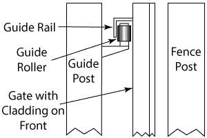
If there is cladding on the front of the frame and gate is on level ground or it is preferred to have the gate at the same height as the fence then a single roller, guide rail and guide post may be used. The guide rail runs the entire length of the gate.
Guide Blocks
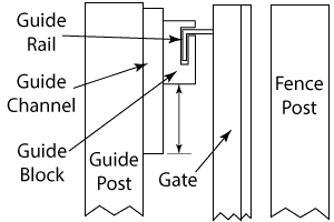
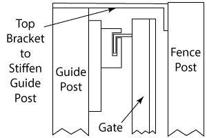
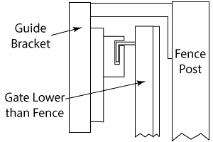
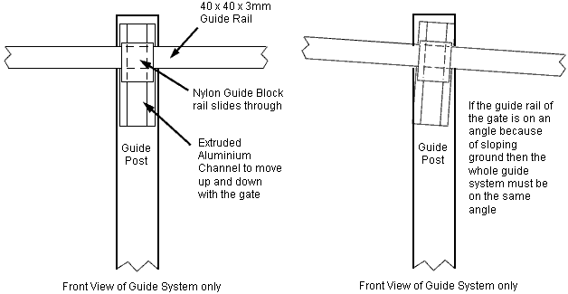
If the driveway has slope across it more than guide rollers can handle then a guide block, channel, rail and post system can be used. A guide rail passes through a nylon guide block as the gate moves, which can move up and down in a channel with the gate. The guide channel can be fitted to a guide post although when a guide post is longer than 1.2m it can shudder a bit as the gate moves, particularly if the driveway is uneven or slopes across. This issue can be resolved by fitting a bracket on the top of the guide post that goes over the gate and attaches to the fence or wall OR a bracket can be fitted to the fence or wall that goes over the gate to the back where the guide channel is. The advantage of the bracket is it is more economic to install and uses less space on the ground where the motor is but does require the top of the gate to be lower than the post other wise the bracket may be visible, the fence must be strong enough and not bow or warp.
Sloping and Uneven Driveways
If a sliding gate is on a driveway that slopes across, is uneven in grade and the top rail is to be raked then a guide rail can be used in place of guide rollers but the channel for the guide block would need to be set at an angle equivalent to the average grade of the slope across the driveway.
Guide Rails not at the Top
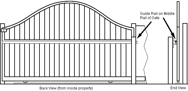
If the top rail is curved or some other shape other than a straight line making it impossible to fit the guide rail, the guide rail maybe fitted on a rail further down .
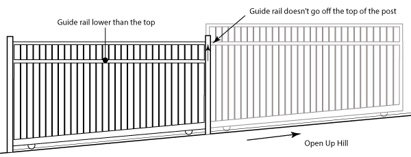
Also if a gate is on a driveway that slopes across and the gate is to slide open up hill the guide rail needs to be set down from the top so the guide post doesn't need to be higher than the fence.
Open Hard Stops and the space they require
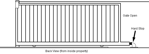
The gate must also be prevented from opening too far because if it does it may come off the guide system and fall over, which can be dangerous.
If using a guide rail and block system on a gate that is on flat ground a tek screw fitted to the guide rail will work effectively as an open hard stop although if the gate is light weight it may derail or if it opens down hill this may not be strong enough. These stops take up no space for the gate to open if they can be used.
If the gate opens up against a solid wall or fence then nothing else is required because the gate will only stop against this once when the motor is being setup and from then on the gate will be stopped short by 10mm or so by the motor, so this is all the stop will add to the amount of space a gate requires to open. The hard stop is really only there for setting the motor up and in case the gate is manually release prevents the gate running off the guides and falling over. A rubber buffer may be fitted to soften the impact if desired but this will add what ever the length of the stop the the amount of space required for the gate to open. Stand alone hard stops that bolt to the footing are available and are the best for gates that open down hill. These require and extra 200mm or so of space for the gate to open.
Guide Systems for Telescopic Gates
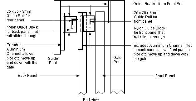
The telescopic gate guide system uses a block and rail guide system for all panel. The back panel can have a guide bracket that fits to a post or wall in front of the gate or can have its own guide post behind the gate. A guide bracket does require the post or wall to be higher than the gate.
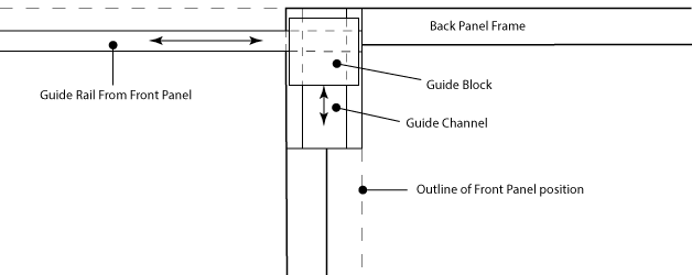
The guide block and channel for the front gate fits on to the back gate positioned in the overlap between the two gates to minimise the space it uses and to conceal it.
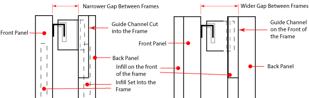
For gates with cladding set in the middle of the frame the guide channel can be cut into the frame to minimise the gap between the two gate frames. If the cladding is on the front then the guide channel will simply be fitted to the front of the frame to get more gap between the frames. If the guide channel is to be cut into the frame, the frame is made from aluminium and the guide channel is at the top of the gate it could be welded directly into the frame otherwise if the frame is made from steel or the guide channel isn't at the top a box will need to made in the cut out so the guide channel can be screwed in.
Placing a Guide Post out of the way.
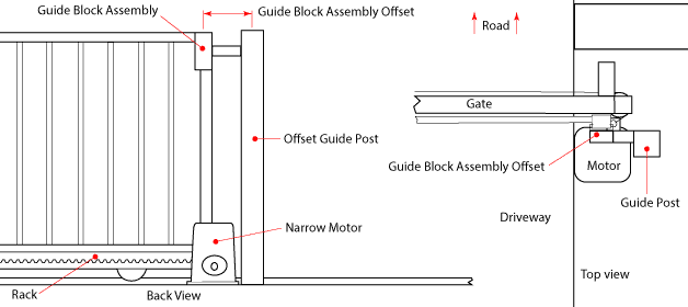
The guide post normally goes hard up against the edge of the driveway. If space is limited, which it generally is for telescopic gates, then the motor must be hard up against the edge of the driveway to keep the amount of space for the gate to open to a minimum. In this case the guide post can be placed on the other side of the motor and have an arm reach over to where the guide block assembly needs to go. This also keeps the back of the motor clear so the user has access to the manual release. This can apply to single panel sliding gates too.
Preventing the gate from being lifted to gain access into a property
If a gate is light weight there is a possibility that a very keen burglar could lift the gate off its track to gain access into your property.
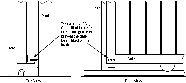
Two pieces of angled steel or aluminium can be used to prevent the gate from being lifted off the track, one fitted to the post and the other to the gate so they line up when the gate is closed. The gap between them should be 5 to 10mm to allow for any ground movement but not too much other wise the wheel can be pulled off the track.